 |
 |
Links to Other Pages and Places |
Example 1: Frequency Modulated CW Radar
 |
Employing Saw Tooth Modulation |
 |
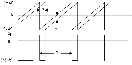
A Continuous Wave (CW) RADAR, employing frequency modulated (FM), can be designed to operate with a wide variety of modulation waveforms. Shown here is a segment of the modulation waveform for an FM RADAR employing linear saw tooth modulation. The frequency is swept over a bandwidth 2Df from fo - Df to fo + Df. Range resolution of a RADAR employing this modulation is approximately the same as for a pulse RADAR of the same bandwidth. |
 |
In the figure above, the upper half shows the instantaneous transmitted frequency, and the instantaneous received frequency of the signal reflected from a target whose round trip time delay is t. The difference in frequency between the transmitted and received signals is a function of the time delay t, and has two distinctively different values as shown in the lower half of the figure. |
 |
The beat pattern, following RF mixing is shown pictorially in the figure below. This pattern is a unique function of range to the target provided t is less than T. In simple embodiments, only the lower frequency region is used, although the full pattern can be used to advantage in some applications. Multiple targets are easily separable in range if the mixing process is reasonably linear. Linearity is generally not a limiting factor since the reference signal is generally large in comparison to the target signals. |
 |
If the modulation is periodic, the spectrum of the beat pattern is formed by lines spaced by the repetition frequency. Targets at different ranges are represented by beat pattern with a different frequency content, and a different time for transition from high to lower frequency. Resolution of closely spaced targets is determined by the transmitted bandwidth 2Df. |
 |
A variety of other waveforms, including sine wave, triangular, pseudo-random sequences, and random noise may also be employed. However, the choice of an optimum waveform is application dependent. CW radars are particularly well suited when Doppler information, as well as position information is required. |
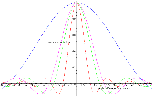
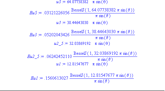
Example 2. Radiation Pattern of a 0.75 inch Diameter Acoustic Transducer
Radiating into Water
at 1, 2.5, 3, and 5 MHz
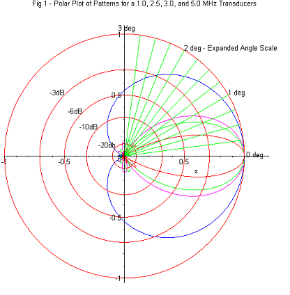
Transducer Polar Plot with Expanded Angular Scale
|
 |

